


Normative and technical support of GPR works
Today, the implementation of non-destructive testing of highways by the GPR method has become increasingly widespread for the tasks of monitoring changes in the thickness of pavement layers, searching for weakened zones in the base layers of pavements and subgrade, searching for engineering communications and solving other applied problems of the road sector
There is a large number of domestic and foreign publications on the experience of using GPR to solve these problems in free access. However, when planning to carry out GPR surveys, the user is faced with a large number of questions, the answers to which are not always easy for him to get. First of all, novice specialists are faced with the choice of equipment. Of course, the selection of equipment should be regulated by both the list of current tasks to be solved and the possibility of their expansion. The highway is a linear long object, along which, depending on the category, traffic with different intensity is carried out. It is obvious that the methodology for the production of ground-penetrating radar works on highways must ensure the proper level of productivity, safety and quality of the result obtained. In Russia today there are several documents regulating the procedure for performing GPR works on highways:
1) GOST 32868-2014 "Highways for general use. Requirements for conducting engineering and geological surveys"
2) GOST R 58349-2019 "Highways for general use. Travel clothing. Methods for measuring the thickness of pavement layers"
3) ODM 218.3.075-2016 "Recommendations for quality control of road construction works by GPR method"
4) ODM 218.2.037-2013 "Methodical recommendations for carrying out survey work during overhaul and repair of highways"
5) ODM 218.4.030-2016 "Guidelines for assessing the carrying capacity of ice crossings"
6) Methodological recommendations on the use of GPR in the inspection of road structures. Ministry of Transport of the Russian Federation. State Road Service of the Russian Federation (ROSAVTODOR) Moscow 2003
At the same time, the implementation of the very first projects with the use of GPR poses a number of questions for the road sector engineers. And finally, at the final stage of the office processing of the results of a GPR survey, the main difficulties arise - the interpretation of GPR data. However, regardless of the equipment used, the general recommendations for performing work are always the same
This article is intended to reveal the features of the performance of certain technological operations from the point of view of practice, incl. to demonstrate the sequential process of work, to obtain intermediate and final results of a GPR survey
As it was mentioned earlier, the choice of equipment for GPR surveys should be determined by the planned tasks. For owners, operators of highways and general contracting road construction organizations, the tasks of operational and acceptance construction control of completed road construction work are relevant. As part of the construction control, the owner of the structure must make sure that the general contractor has completed the arrangement of the layers of the road structure in accordance with the design solutions in terms of their required thickness and uniformity of properties. In turn, the general contractor must have an accurate and objective picture of the compliance of the completed road construction work with the requirements of the project documentation to maintain the proper level of business reputation. To solve these problems, as a rule, mobile road laboratories are used, equipped with a subsurface sensing system with antenna modules that work with separation from the surface (Fig. 1). At the same time, the main guiding documents are GOST R 58349-2019 and ODM 218.3.075-2016
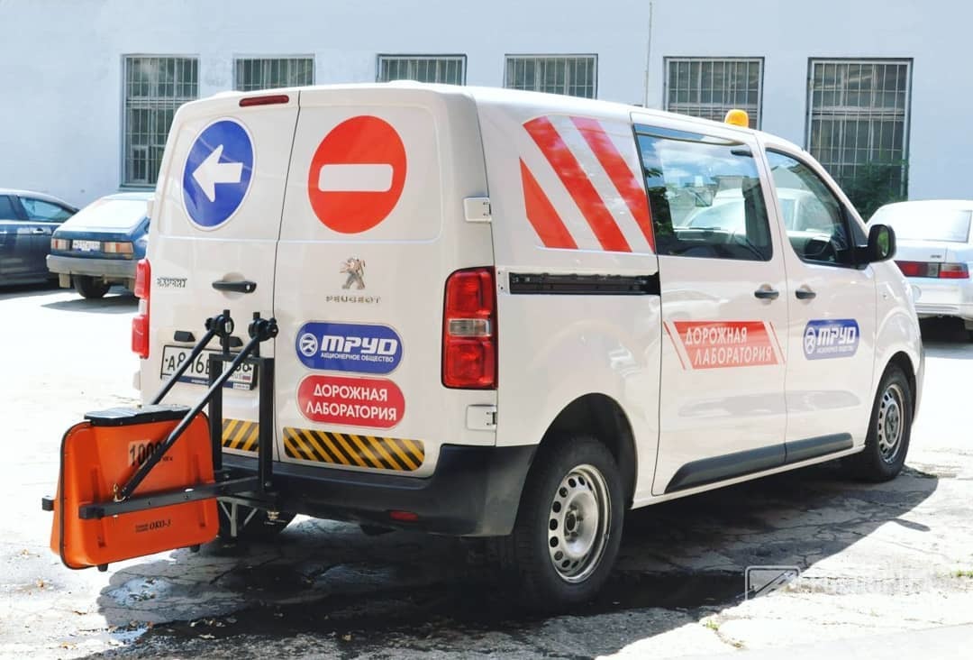
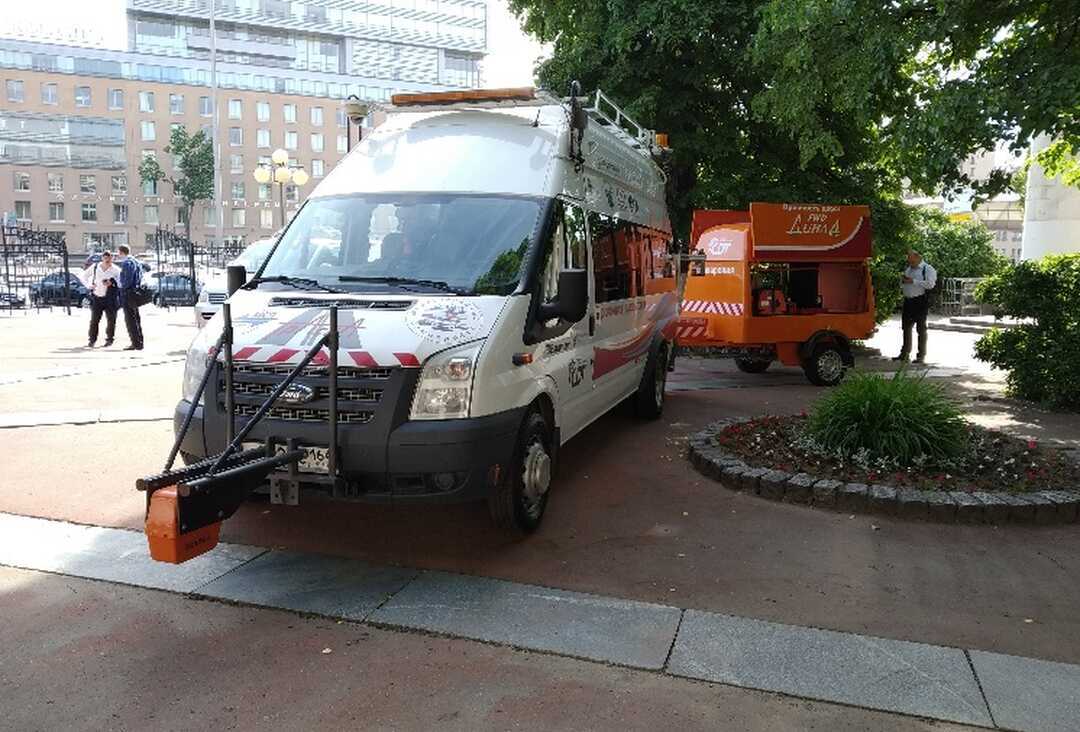
Figure 1 - Mobile road laboratory with a hinged GPR antenna module
Such solutions have undeniable advantages: stationary fastening, high performance and safety of data collection, relatively large autonomy and payload on the carrier, the ability to integrate with other measuring devices. The disadvantages of the solution are: relatively small scanning depth, the impossibility of performing a survey of local places, for example, slopes of excavations and embankments of the subgrade, the ground base of the subgrade, etc.
For design and survey organizations, the tasks of assessing the actual structure and condition of road structures, the place of structural change, the homogeneity of the subgrade soils, the presence and position of engineering communications under the structure in order to select the most optimal design solutions for the planned road construction work are more urgent. The use of GPR in engineering surveys is regulated by GOST 32868-2014, ODM 218.2.037-2013, ODM 218.4.030-2016, as well as "Methodological recommendations for the use of GPR in the inspection of road structures" (ROSAVTODOR, Moscow 2003). In this case, GPR equipment can have a set of more versatile functions: be able to be installed both on a vehicle and on platforms for pedestrian imaging (Fig. 2)
The advantages of such systems are the ability to perform surveys with a dense network of GPR passages to a relatively large depth, incl. in hard-to-reach places. Limitations of the solution are significantly lower data collection performance and complexity of work in traffic conditions, limited operating time from portable power sources
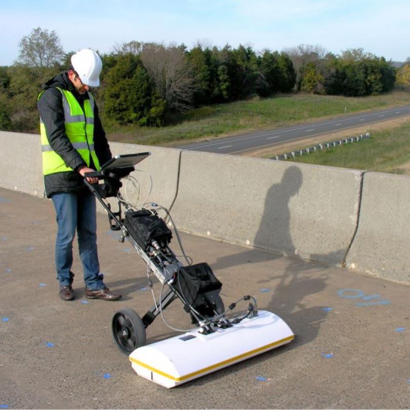

Figure 2 - GPR complex with a contact antenna module
Regardless of the type of subsurface sensing system, it is necessary to correctly select the central frequency of the antenna modules, taking into account the problem being solved. As a guideline when choosing an antenna, it is necessary to remember that a specialist always has a choice: high resolution in depth or maximum scanning depth. Even multi-frequency GPR operating on the technology of step change of frequency with a wider range of frequencies have similar selection limitations
As an example for determining the thickness of layers of road structures, one can cite the requirements of GOST R 58349-2019 (Table 1), where the correspondence of the central frequency to the ranges of the scanning depth is determined
Table 1 - Center frequency of antenna units for measuring the thickness of the layers of the pavement and base of the road structure

For deeper surveys in order to assess the uniformity of soil properties, it is advisable to be guided by the requirements of ODM 218.3.075-2016 (Table 2)
Table 2 - Recommended frequencies of antenna units for assessing the homogeneity of the properties of materials and soils of the subgrade

The error and reliability of the results of a GPR survey are primarily determined by the methodology for performing field work. Despite the rather detailed requirements and recommendations of GOST R 58349-2019 and ODM 218.3.075-2016, in practice the engineer always encounters the personified features of the object being inspected. In this case, the following general rules must be followed:
1. Prepare to areal visit in advance. Analyze and keep in memory the initial information: the results of engineering survey reports (type and depth of soil occurrence, ground level groundwater level, the presence of specific soils and hazardous processes), design solutions (embankment height and excavation depth, features of the drainage system, design diameter), diagnostic results (characteristic defects), the results of the analysis of the video recording of the passage from the car DVR, map services, etc.
2. Always carry out a areal reconnaissance survey. Analyze the terrain and natural migration routes of surface waters, record the sections of the embankment transition to the excavation and vice versa, the location of culverts, the presence of defects in the road surface and subgrade, areas of stagnant surface water on the road surface and at the base of the subgrade, other significant features at the facility
3. Record in the log the peculiarities of weather and climatic conditions: air temperature, condition of scanned coatings during work after precipitation
4. If the equipment allows you to flexibly adjust the parameters, select empirically the time base to achieve the required scanning depth. The scanning step should not be too large or very frequent for the tasks being solved. When recording very short GPR profiles with a length of several meters, for example, when examining elements of prefabricated structures, the sanitation step can be within the first millimeters. When surveying on foot profiles of short lengths of several tens of meters, the scanning step of high-frequency antennas can be within the first centimeters. In all other cases, when examining objects with a length of hundreds of meters or several kilometers, the scanning step can be within the first decimeters for any types of antennas, but you should not take a scanning step of more than 30 cm for high-frequency antennas
5. In order not to return, collect as much data and information about the areal as possible within the time allotted for the field. Often, redundant information greatly simplifies the process of cameral data processing. This does not mean at all that all information collected in the field is subject to processing and analysis. But in case of controversial issues, it will be a backup source of data to establish an objective picture. An example of this rule can be a simple photographing of a work site, when, during office processing, questions arise about identifying the bindings of a specific place or the presence on the GPR profile of artifacts of unknown origin (for example, interference from a barrier fence or a parked car)
6. Try not to work without gridding. Even having connected satellite equipment of low accuracy class to the GPR, during the cameral processing, there will be a general idea of the actual distance traveled, where, in what sequences and directions the GPR profiles are recorded. Using satellite equipment of a geodetic class, in the absence of the possibility of operating in RTK mode, configure the receiver to transmit information about coordinates to the GPR in an autonomous mode (for example, via the NMEA protocol), while simultaneously recording field observation files (for example, RINEX) to the receiver itself. When recording short straight-line GPR profiles without a coordinate reference, fix the coordinates of the points of the beginning and end of the profile using any geodetic survey equipment (total station, satellite equipment). Coordinate calibration drilling sites. Measure the height of separation of the proximity antenna from the scanning surface and be sure to record the distance of the GPR antenna offset relative to the satellite equipment antenna
7. If possible, carry out transverse passes of the GPR on the road from curb to curb, in case of high traffic and the absence of a specially organized temporary blockage of traffic, record data in the alignment of regulated and unregulated pedestrian crossings. If it is not possible to record a transverse profile, use the longitudinal parallel profiling technique
The greatest attention should be paid to the issues of cameral processing of GPR data
Before the start of the production of cameral works the initial data should be analyzed, and field materials should be collected and systematized:
- records of the observation log about weather and climatic conditions
- GPR profiles
- trajectories of movement of GPR equipment according to different configurations of equipment (different antenna modules) and periods of data recording
- parameters of the displacement of the GPR antennas relative to the receiving antenna of the satellite equipment
- acts of drilling and sampling (for calibrating the thickness of layers)
- test reports for road building materials (to assess the homogeneity of properties)
- digital model of the situation and relief
- photographic materials
The cameral processing process can be conditionally divided into components: preliminary and final cameral processing
Preliminary cameral processing is carried out after a GPR survey, but before excavation work. Within the framework of this task, the operator must analyze the GPR profile and find on it the places for coring or drilling wells. For example, in accordance with ODM 218.3.075-2016, it is important to select areas on the radargram where the sought boundaries are clearly and unambiguously displayed, while it is recommended to take cores (samples) in areas with the maximum and minimum layer thickness. As an example, Fig. 3 shows an image of a radargram recorded by an antenna unit with a central scanning frequency of 1700 MHz on a road section that has been in operation for a long time. In accordance with the depth scale, it can be seen that the thickness of the layer of asphalt concrete material is in the range from 10 to 23 cm. Despite the fact that the radargram is presented over a rather short section with a length of just over 500 m, the presence of variability in the layer thickness is obvious. A similar picture is observed with the underlying layers (crushed stone-sand mixture, sand). Within the framework of a GPR survey, it is necessary to select both places with relatively uniform interfaces between layers, and places with local decreases and increases in thickness. Subsequently, it is necessary to take out the selected places on the ground in order to carry out calibration drilling in them

Figure 3 - Justification of drilling places
Since TIM LLC uses in its work the methodology of complex GPR surveys, including accurate geodetic referencing of data, the drilling sites are determined with a coordinate reference. In the production of GPR works, a bundle of GPR equipment of the Oko-3 or TerraZond series, as well as GeoScan32, GeoLocator (for data collection) and GeoReader (for cameral data processing) software systems is often used. All GPR profiles recorded in the course of work are loaded into a single software environment. The operator opens the files of the GPR project one by one and marks the locations of future wells in them. Then a text file is created with the coordinates of the planned wells. The specified file can be loaded into the GIS to assess the uniformity of the distribution of wells along the route (Fig. 4) or into the controller of satellite equipment for the removal and fixing of drilling points on the ground
 Different colors can indicate different types of workings (cores, wells, pits, etc.)
Figure 4 - Trajectory of the GPR movement with marked drilling places
It is important to remember that unauthorized changes in the location of excavation by drilling engineers are not allowed, since the cameral engineer assigned them in other places and simply will not know about the fact of displacement. If restrictions are found on the ground that impede the execution of drilling operations in pre-designated places, the field engineer must inform the cameral department about this, if possible, agree on a new place of drilling operations and be sure to coordinate it. This rule must certainly be fulfilled both for longitudinal and transverse well transfer, since the variability of the road structure can be caused both by technological errors in the performance of road construction works, and by design solutions. For example, in the case of differences in the design of the road pavement in the lanes and on the fortified shoulder, this will be seen on the transverse GPR profiles (Fig. 5)
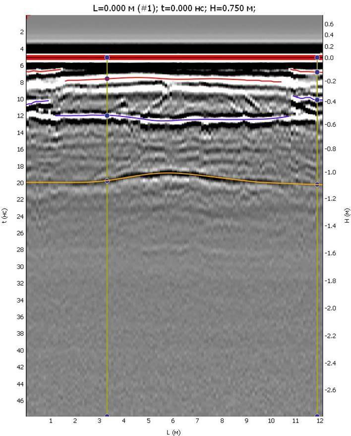
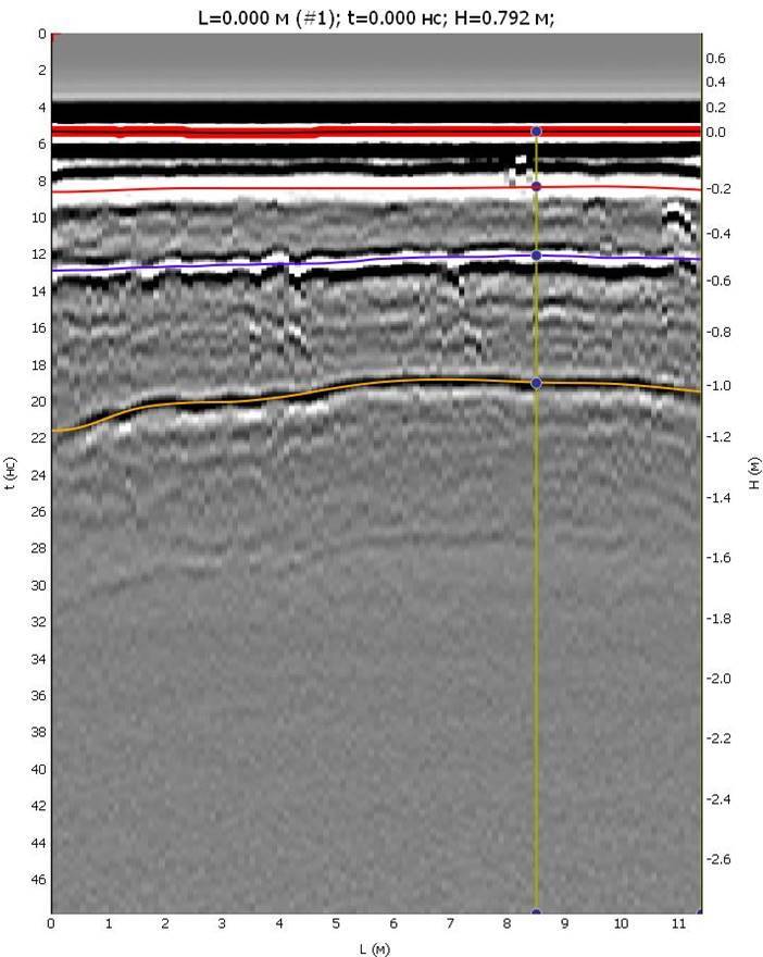
Figure 5 - The difference in the design of the pavement on the lanes and on the fortified shoulders
It is better to determine the thickness of the layers of the base of the pavement along the wall of the working (pit, borehole), since this will provide a minimum measurement error. This rule should be paid the most attention during operational and acceptance construction control, performing measurements in accordance with GOST R 58349-2019. In the case of engineering surveys, the thickness of the layers can be determined by samples of materials and soils extracted from the mine
Final cameral processing is carried out after driving and documenting the workings. The thickness of the layers, determined from the results of destructive methods, is used to calibrate the GPR profiles, but first you should pay attention to the detection of boundary of the section environments
The interpretation of radargrams recorded by contact and proximity antennas differs in that the search for the scanned surface is performed differently
When using contact antenna units, the scanning surface corresponds to the first reflections on the radargram (Fig. 6)

Figure 6 - Interpretation of the scanning surface for a contact antenna
When using contactless antenna units, the scanning surface corresponds to the second reflection on the radargram (Fig. 7)

Figure 7 - Interpretation of the scanning surface for a non-contact antenna
Comparing the scanned surface in Figures 6 and 7, you can see that contact antennas have a flat surface, while non-contact ones do not. This is due to the vertical rolling of the proximity antenna on the vehicle suspension, therefore, vibrations of the reflective surface on the radargram are also permissible
The boundaries below the scanned surface are the boundaries of the various structural layers. As a rule, the layer structure is well pronounced on newly constructed road structures. It is usually more difficult to distinguish layers on long-term exploited highways due to the stratification of boundaries with traces of numerous repairs. Therefore, to establish a more objective picture of the internal structure of road pavements at such facilities, more drilling is required
Of course, within the framework of one article it is impossible to take into account all aspects of the correct execution of GPR works on highways, therefore the only correct solution is to accumulate and take into account one's own practical experience. At the same time, experience alone is not enough to obtain a high-quality result. You need easy-to-use and reliable tool
At one time, the engineers of TIM LLC faced the problem of a limited choice of such tools in our country and went along the path of creating their own solution, the name of which is the GeoReader Software package. What are the advantages of our solution and how does it differ from the solutions of our competitors?
First, the development of the GeoReader Software package was not aimed at commercializing the software. The entire set of capabilities and functions met one single task - to make the result of a GPR survey as objective as possible. This was required by scientific and commercial projects in which our engineers and authors of the software took part as performers
The techniques used in the GeoReader software for transforming the time section into the depth section are characterized by maximum pretentiousness, which allows you to most accurately determine the actual thickness of the layers of the scanned medium, and in combination with an approach similar to the most popular CAD solutions in terms of scaling the working area, the maximum resolution is provided in horizontal and vertical when vectorizing layer boundaries and point elements
An important feature of the GeoReader Software is a large set of functions that allow high-precision georeferencing of GPR profiles. Many who have worked with GPR data know how difficult it is to achieve realistic limits for the spread of the propagation velocity of an electromagnetic wave in the same layer, but in different areas. Often, the results of drilling introduce contradictions into the overall picture of velocities after the calibration of the GPR profile by workings. This is primarily due to inaccurate positioning of wells / pits and cores on the GPR profile. GeoReader is not just a product that has a certain set of technical capabilities for high-precision referencing, but a tool for detecting gross errors made in field work with a GPR. In addition, TIM LLC has developed methods of work production, which are as versatile as possible. They do not carry the goal of promoting the sales of equipment of a certain manufacturer, but only help engineers to correctly collect GPR data
Secondly, GeoReader is not a “thing in itself”. The software package has a wide range of capabilities for data exchange with other CAD and GIS applications, both in terms of import and export of data. GeoReader actively develops the idea of complex surveys in which the GPR is not the only source of information about the surveyed object. To date, not only support for data from GPR of various production has been implemented, but also integration with data from FWD dynamic loading units, mobile diagnostic road laboratories. GeoReader allows you not only to receive maximum information from GPR data, but also to carry out their joint analysis with data obtained by other methods
Thirdly, GeoReader possesses a set of the best experience collected from the analysis of domestic and foreign software products. For example, GeoReader supports data from such GPR equipment as OKO and LOZA. At the same time, each of the brands has its own software for data processing, and the engineers of TIM LLC are aware of the capabilities and limitations of each of the software products. When developing GeoReader, all the best capabilities of the standard software of GPR equipment by OKO and LOZA were taken into account, as well as new functions were added to make data processing more convenient. At the same time, there are possibilities for the simultaneous use of both the standard software of the OKO and LOZA GPR, and the GeoReader to solve a larger set of tasks
Taking into account the fact that domestic GPR equipment is more widespread on the territory of Russia than foreign ones, due to the use of the GeoReader Software package, additional opportunities appear to increase the efficiency of the results of GPR survey. As for foreign counterparts, it can be noted that the quality of domestic products in the context of forced import substitution in recent years has significantly increased. GeoReader, like other Russian products, is constantly evolving taking into account global trends
To learn more about the GeoReader Software package, we suggest you send a questionnaire to post@geotim.ru to receive a trial version, as well as study the presentation: